
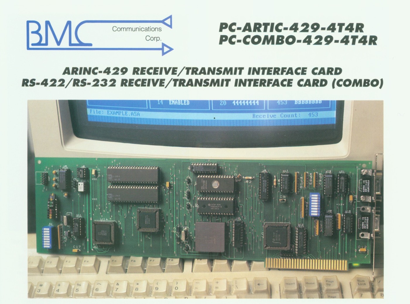
PC ESA ARINC BOARD
• Up to 4 Transmit and 4 Receive Channels
• Efficient board to Host Protocol, Interrupt-driven or Polled
• I Transmit and 1 receive RS-422/RS-232 Channel (Combo)
• Operates in any PC/XT/AT/386 or compatible computer
• Programmable Transmit and Receive Buffer Size and Modes
• Powerful 16 bit microcontroller on board
• Interrupt driven Multitasking Real Time Operating System Firmware
• 36 Kilobytes of Data Memory on board
• Programmable ARINC parameters and Transmit voltage Amplitude for each channel
• Programmable internal Receive/Transmit Loopback
• Diagnostic EDS on board
• Extensive Software Support, development tools and programs included
PC-COMBO-429-4T4R
PC-ARTIC-429-4T4R
The board features:
• Up to 4 ARINC Transmitter channels
• Up to 4 ARINC Receiver channels
• Programmable ARINC parameters
Data Rate: 100 Kb or 12.5 Kb
Word Length: 32 or 25 bits
Parity: Odd or Even
SDI: on, off, SDI bits
• Programmable Amplitude Voltage
• 1 Transmit and 1 Receive RS-422/232 channel
• Programmable transmit/receive loop back mode
• Programmable pre-transmission time delay
Programmable Receive filter.
TRANSMITTING CODES
NORMAL MODE: The board transmits a data buffer (up to 950 ARINC Words). Upon termination, a Status Flag is set and an optional Interrupt Request is posted.
LOOP MODE: The board transmits a given buffer (up to 950 ARINC Words). Upon termination, transmission is repeated until a STOP command is received. Data being transmitted can be changed without stopping the operation. A Status Flag is set and an optional Interrupt Request is posted every time the last word in the buffer is transmitted.
LABEL MODE: The user specifies for each desired label its data value and a time interval. The board then periodically transmits each specified label at its specified period without interruption of operation. The labels and Periods can be changed without stopping the operation.
RECEIVING MODES
In all receiving modes, a user written 256 bit Label Mask is applied to the received data, enabling to pre-filter non-relevant labels. Label-filtering is disabled by filling the mask with 1-s. In addition to the operations described below, each time an ARINC data word is received in any of the receiving modes, a Status Flag is set and an optional Interrupt Request is posted.
NORMAL MODE: The board store a data buffer (up to 950 ARINC Words). Upon termination, a Status Flag is set and an optional Interrupt Request is posted.
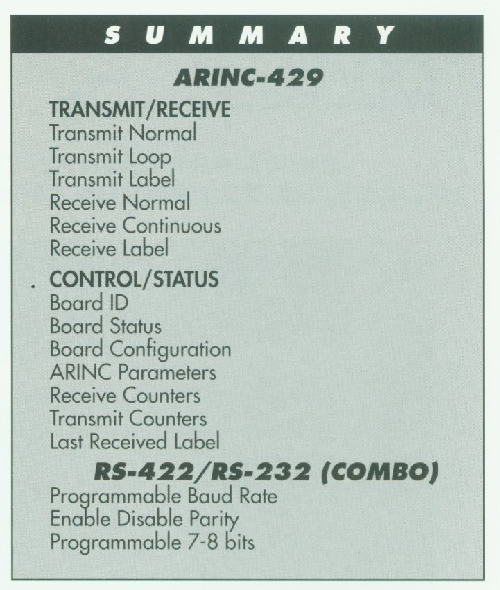
CONTINUOUS MODE: Received ARINC data words are stored in a user-specified buffer (up to 950 ARINC words). When the buffer is full, the buffer “wraps around “acting as a circular buffer Each time the receive count is a multiple of the buffer size a Status Flag is set and an optional Interrupt Request is posted. Receiving is terminated using the STOP command. A Status Flag and an optional Interrupt Request are posted when the Receive Buffer is half- full as well. The board can be set to send an interrupt request when it receives a particular label.
LABEL MODE: Received ARINC data words are stored in a user-specified 256 words long buffer Each cell in the buffer corresponds to Label value. Each time a data value is received on the Bus, the board stores it in the corresponding cell. Receiving is terminated using the STOP command.
CONTROL/STATUS FUNCTIONS
The above receiving and transmitting modes are supplemented by a cluster of Control and Status functions via which the user can specify additional conditions and modes of operation and receive from the board Status and Data such as Receive Count, Channel Status, System ID, Last Received Label and more.
APPLICATION PROGRAM INTERFACE
All the above-described operations are performed
via software function calls from the supplied
Application Program Interface.